A Two-Stroke Internal Combustion
Engine
This invention relates to a two-stroke internal combustion
engine for application in motor vehicles of all types.
The principal feature of the invention are two variable cross-section
cylinders located in the body of the engine 1. Each of these
cylinders has its upper part smaller than the lower one. The
cylinders are linked together by inlet channels (30), each
of them linking the larger section of one cylinder with the
smaller section of the adjacent cylinder. Fitted to each cylinder
are variable cross-section piston (2, 3). On both ends of
the crankshaft (10) are variable opening angle cams which
are responsible for the control of valves (14, 15).
A valve located in the bottom part of the last cylinder (bottom
valve) is provided with a fork-type push rod.
This invention relates to a two-stroke internal
combustion engine (i.c.e.) for application in motor vehicles
of all types.
The construction that is most similar to the proposed one
is a fuel injection two-stroke i.c.e. with two cylinders and
pistons which are linked via connecting rods to the crankshaft.
The crankshaft and the connecting rods are supported on journal
bearings in the crankcase which is closed from the bottom
with the oil pan. From the top the cylinders are closed with
engine heads which are provided with valve and exhaust channels.
The latter are linked together forming a manifold which houses,
in its further section, the exhaust gases catalyst. The body
of the engine houses also cylinders and pistons of a blower.
On the top of the blower cylinders there are engine heads
with inlet and outlet valves, inlet channels, the outlets
of each one is located in the adjacent cylinder just above
the piston crown in its bottom dead point. There are two constant
opening angle cams machined on both ends of the crankshaft
which govern via push rods the operation of the exhaust valve.
The inlet channels to the blower are linked into one air channel
which houses a throttle which is linked to the accelerator
pedal.
The main deficiency of the two-stroke i.c.
engines currently used consists in a high toxicity of exhaust
gases. It depends mostly upon the degree of oxidation of fuel,
which is the higher the more air is supplied into the combustion
process, as well as upon the efficiency of purification of
the exhaust gasses in the catalyst. The presence of the exhaust
gases in the air reduces the oxygen contents. Therefore, to
improve their composition, they are separated from the air
that is contained in the air mixture. Especially good results
are obtained in direct injection i.c. engines equipped with
controlled exhaust valves and air blowers. This auxiliary
equipment, however, make the engine more complicated and heavy.
Ultimately, it becomes comparable in this respect with a four-stroke
i.c.e. without matching the purity of the exhaust gases of
the latter.
The subject of the present invention is
a two-stroke i.c.e. In the body of the engine are cylinders
and reciprocating pistons which transfer power to the crankshaft
via connecting rods. The crankshaft is supported on journal
bearings located in the crankcase closed with the oil pan.
From the top, the cylinders are closed with engine heads which
are provided with valves. There are two cams machined on both
ends of the crankshaft.
The principal feature of the invention is
a variable cross-section cylinder with its upper part smaller
than the lower one. The cylinders (at least two) are linked
together by inlet channels, each of them linking by passageways
the larger section of one cylinder with the smaller section
of the adjacent cylinder. Fitted to each cylinder is a variable
cross-section piston. On both ends of the crankshaft are variable
opening angle cams which are responsible for the valves control.
A scraper ring is located at the lower part of the piston.
A valve located in the bottom part of the last cylinder (the
bottom valve) is provided with a fork-type push rod.
The design of the proposed engine is more
simple and compact as compared to a four-stroke i.c.e. As
a result, the engine is more light. This statement is additionally
validated by the two-stroke mode of operation. By virtue of
a more efficient separation of the air and the exhaust gases
the burning of the mixture is better than in the known two-stroke
engines. Moreover, a larger volume of the air in the cylinders
and the catalyst enables a better burning of the mixture in
the case of a partial development of the maximum power than
is the case in four-stroke i.c.engines. In the latter case,
better efficiency may be anticipated too.
Additionally, since the volume of the blower
is higher than the volume of the cylinder, the exhaust gases
are efficiently removed when the cylinder is fully filled.
The process is even more efficient when3 as a result of a
partial development of power3 the opening time for the exhaust
valve is being prolonged to decrease the filling ratio. The
unused air supplied by the blower is delivered to the exhaust
system increasing the efficiency of the catalyst. This is
specially important because of ecology: the lower is the cylinder
filling ratio, the worse is the composition of exhaust gases.
In the proposed invention, the filling ratio may be increased
and, as a result, it is possible to improve not only the composition
of exhaust gases but the efficiency of the engine. This is
possible in situations where the demand for power is less
than 50 % of its maximum rated value: in such cases one cylinder
may be switched off and set to idling. With the exhaust valve
of the eliminated cylinder constantly in the off position,
this system is transformed into a pump that is pressing air
to the exhaust system of the engine improving thus the efficiency
of the catalyst. The resistance to motion of the non-working
system (working cylinder3 piston3 associated blower) decreases,
and the exhaust gases entering the non-working cylinder provide
the heat that keeps the system ready for operation. The other
system must develop in such cases greater power. This requires
the increase in its filling ratio and consequently3 its efficiency
increases too.
With the valves permanently opened it is
possible to start the engine with an electric machine instead
of a starter. This machine may be employed3 apart from charging
accumulators with the engine3 to a recuperation-based braking
of the vehicle and its propelling at cross-roads, stops, and
specially in traffic jams, which is ecologically advantageous.
When charging the engine in agreement with
the proposed invention, the heat recuperated during its cooling
may be utilised in two ways. Firstly, with the application
of a high capacity blower, as described above, it is possible
to use the energy of exhaust gases in a turbine coupled to
the crankshaft or any other axle of the vehicle. Secondly,
with the application of a blower this energy may be employed
to drive the crankshaft when filling the blower with air.
The blower operates then as an air engine and its high capacity
is not necessary. The described engine is basically an Otto-cycle
engine (low compression) but it can be also a Diesel-cycle
engine (high compression). In the latter case the cams may
be with constant opening angles.
The design of an engine in agreement with
the proposed invention may be significantly simplified: as
is the case in all currently used two-stroke i.c.engines,
the eliminated system may be designed without valves when
loading is partial.
The preferred embodiment of the invented
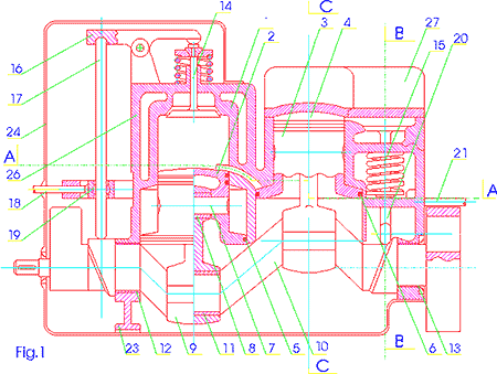
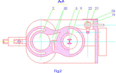
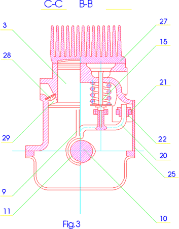
engine is illustrated in Fig. 1 (cross-section, side view),
Fig. 2 (cross-section, top view), and in Fig. 3 (cross-section,
front view).

Version 1
A two-stroke i.c.e. consists of the body 1 with two variable
diameter cylinders and inlet channels 30 between them. The
two cylinders are fitted with variable diameter pistons 2
and 3 respectively, each of them provided with a compression
ring 4 and scraper rings 5 and 6. The pistons 2 and 3 receive
each a piston pin 7 supported on a bearing 8 which is located
at the smaller end of a connecting rod 9. From the other end
the connecting rod 9 is supported on a journal bearing 11.
From the left side the crankshaft is supported on a sliding
bearing 12 in the body of the engine 1, and from the right
side3 on a sliding bearing 13. To the left from these bearings,
variable opening angle cams are machined, which govern the
operation of valves 14 and 15. These valves may be designed
either as an upper one (14) or a lower one (15). The shank
of the valve 14 contacts with one arm of a rocker 16.

The other end of the rocker contacts with
a pushing rod 17, the lower end of which is actuated by a
cam machined on the crankshaft 10 and guided by a slider 18
with a spherical sliding insert 19 which is free to move in
the body 1. On the shank of the valve 15, a fork-type push
rod, which is free to rotate, is mounted. One end of the rod
is actuated by a cam that is machined on the crankshaft 10,
and the other end is located in a second slider 21 with a
sliding insert 22. The body of the engine is closed from the
bottom with the oil pan 24; from the left side3 with the side
cover 24; and from the rear side3 with the rear cover 25.
The left cylinder is closed from the top with a liquid cooled
engine head 26 and the right cylinder - with an air cooled
engine head 27. At the inlet to the lower part of the cylinder
(with the larger diameter) are plates of inlet valves 28 which
are fixed with screws 29. From the left side on the crankshaft
10 there is a counterweight balancing the engine in the vertical
plane, and on the right end there is a flywheel with a displaced
centre of gravity which provides for the balancing of the
engine.

The operation of the engine is as follows:
When the piston 2 or 3 travels from the top dead centre to
the bottom dead centre, the air is sucked by its larger section
through the opened plate of the inlet valve 28 to the cylinder.
When the direction of the piston movement changes, the plates
28 close the inlet of air allowing thus for a partial compression
of the air until the inlet channel 30 in the adjacent cylinder
has been opened. The air is forced to this cylinder, and the
gases from this cylinder are exhausted at the same time. Before
the outlets of the inlet channels 30 have been opened, the
vales 14 and 15 open which allows for the removal of the exhaust
gases and next, depending upon the cylinder filling ratio,
for the removal of the air. The cams machined on the shaft
10 push the ends of the push rods 17 and 20 and lift via the
rocker 16, or directly, the shank of the valve 14 and 15 respectively.
The timing of the valves 14 and 15 is adjusted by fixing the
point of contact between the end of the push rods 17, 20 with
the cams machined on the shaft 10 using the sliders 18 and
21, the position of which is governed by the accelerator pedal
and the fuel injection pump. The smaller is the filling ratio,
the greater is the opening angle of the valves 14, 15. Ultimately,
the valves are fully opened. To avoid the excessive wear of
the cams which is associated with this situation, the end
of the push rod may be located on the housing of the bearing
of the crankshaft 10. To increase the efficiency of the braking
effort developed by the engine, the housing may be provided
with a recess which adopts the end of the push rods and produces
a partial closure of the exhaust valves. The application of
the lower valve 15 may simplify not only the design but may
also improve the combustion process and the engine efficiency.
The cross-sections of the engine are circular.
Version 2
A two-stroke i.c.e. in agreement with the version 1 but with
an oval cross-section of the cylinders and pistons 2, 3. The
application of an oval cross-section will result with an increased
capacity of the blower at the same length of the engine. This
enables also the blowing of the cylinder with air from inside
so effectively that its external cooling is no more necessary
as is the case with the cylinder and its piston 3. On the
other hand, the head of the cylinder, which may be designed
likewise the head 27, may be cooled with the additional air.
Patent claims
- A two-stroke internal combustion engine
which has a body fitted with cylinders which are linked
via push rods with the crankshaft which has two cams machined
on its opposite ends and which is supported on its two opposite
located journals with sliding bearings which are mounted
in the crankcase which is closed from the bottom with the
oil pan and from the top with engine heads which are provided
with valves3 the engine being unique in the fact that it
has the body (1) fitted with at least two cylinders which
are larger at the bottom and smaller at the top and are
linked via channels 30 where each channel links the larger
section of one cylinder with the smaller section of another
cylinder, each of the cylinder being fitted with a variable
cross-section piston linked with the crankshaft (10) which
has two variable opening angle cams machined on its both
ends.
- An engine as defined in claim 1 being
unique in the fact that a scraper ring (5, 6) is located
at the larger cross-section of the piston (2, 3).
- An engine as defined in claim 1 being
unique in the fact that the valve (15) which is located
in the lower section of the last cylinder is a lower valve
(15) and is provided with a fork-type push rod (20)
|

